
 The Lambda 001 motor was designed by Nicholas McKinney from Lambda Acoustics Inc. Designed over the period from 1997~1999, tremendous effort was put into creating the lowest possible distortion. The Lambda 001 motor now lives on in the woofers manufactured by Acoustic Elegance, LLC. Below are the details describing the intricate workings of the low distortion motor design.
Defining the Requirements for a Low Distortion Driver
The ultimate design for low distortion should have the following characteristics:
(1) Linear magnetic flux levels across the entire VC movement range.
(2) The flux should be fixed permanently and not move, this is however not the case in 99% of speakers.
(3) High heat absorption properties as close to the VC as possible. The VC, if allowed to heat significantly, will lower the speaker output SPL very quickly.
(4) Linear inductance as the VC moves through its entire range if the driver has to contribute ANY output above the impedance minima above the Fs of the driver. This is not just at the crossover point, this is any output that is not -48dB down in our opinion. The only way to accomplish this is to keep the CORE of the VC the same at all excursions. The VC is after all an inductor. However this is the only inductor in the whole audio system that varies its value with low bass excursion. The low bass creates massive excursions that at the same time change the parameters of the driver at higher frequencies with every inward and outward stroke.
Examining the traditional options
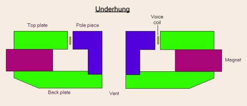 To accomplish the above requirements, only one traditional motor design comes close immediately. The Underhung. The Underhung uses a tall gap plate with a short coil. The flux is quite evenly distributed throughout the gap leading to a very flat BL curve throughout the entire linear operating range of the coil.
(1) The flux level is the same as long as the VC stays in the gap
(2) There is a large amount of steel to absorb the heat from the coil.
(3) No matter where the VC is in the gap the steel core is the same, forcing its inductance to stay linear with excursion.
However, has 4 problems to consider as well.
(1) For any significant power handling, the VC diameter must increase. This raises overall inductance and significantly increases cost.
(2) It needs a much larger motor structure than an overhung as only a portion of the flux in the gap is being used at any given time. Again this leads to more cost.
(3) As the coil leaves the gap the Bl drops very quickly and the driver immediately compresses the output. For this reason you need to keep the driver operating within its excursion limits at all times.
(4) And most importantly, WE STILL CAN NOT KEEP THE FLUX FROM MOVING IN THE GAP.
Fixing the Flux in the Gap
This issue with flux moving is a severe distortion problem in loudspeaker motors. The flux stays fixed only when the VC is stationary. As current is applied to the coil, it becomes an electromagnet. As this new electromagnet travels through the gap, it moves or “modulates” the flux field created by the permanent magnet. The more current applied and the farther the coil moves, the more the flux moves and the greater the distortion. The solution is to fix the flux in the gap to eliminate this distortion. There are 2 basic methods for lowering this effect.
(1) Lower the electrical conductivity of the pole piece. This typically means using extremely expensive materials and/or sacrificing more Bl. One group of materials of interest would be iron/cobalt alloys such as Hiperco 27 from Carpenter. The problem is the extreme high cost which could increase the driver cost by a factor of 10. Another option would be powdered iron. While this is an electrically non-conductive material, it is still magnetically permeable. The drawback is that it is not as highly magnetically permeable as low carbon steel. A loss of approximately 20% of the flux in the gap can be expected due to the lower permeability.
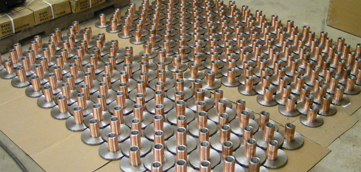 (2) Permanently mount a highly conductive layer that is not magnetic between the VC and the pole. This cannot be a moving piece like an aluminum VC former. It needs to be a rigidly mounted layer, much thicker than the typical VC former. We have implemented this option in what we call our Full Copper Faraday Sleeve (FCFS). This is an extremely large shorting ring which is applied in a proprietary process here at our facility. It is what makes the distortion characteristics of the Acoustic Elegance woofers different than anything else available at any cost. We had a unique, .025″ thick copper tubing drawn to our specifications. As you will see, this copper tubing successfully meets our goals for fixing the flux and also has several additional benefits.
Benefits of the Full Copper Faraday Sleeve (FCFS)
With this permanently mounted highly conductive layer, any flux movement creates large currents (Eddy Currents) in the copper that can now short themselves out. This causes the magnetic flux lines to be electrically shorted to their original location so they cannot move. The devices used for this are called Shorted Turns or Faraday Rings. The benefit is a great reduction of distortion and overall inductance of the driver, as well as linear inductance throughout the stroke.
In addition to the benefits in terms of distortion, FCFS is not only is it highly electrically conductive, it is also highly thermally conductive. The motor has a very large thermal reserve in the steel components. They can absorb a lot of heat. While steel is able to absorb high amounts of heat quite well, it does not do so very quickly. For optimum operation, the voice coil needs to quickly dissipate the heat that is generated as power is applied. If this is not done, the VC temperature will rise leading to an increase in the resistance of the wire. This is known as power compression. As this happens more power needs to be applied to the voice coil to keep the output the same. A cycle is created that cannot be overcome. The voice coil at some point absorbs double (3dB) and even quadruple (6dB) the input power for no apparent gain in output Spl. The FCFS is located in very close proximity to the voice coil at all points in travel. This allows the copper to quickly pull heat from the voil at all times. The heat is then dissipated from the copper into the steel pole through direct contact. No matter what position the voice coil is in, the copper is there to pull heat away.
The Lambda 001 Motor is Born
 In the picture you will find a full color cutaway of the Lambda motor design. Notice the highly extended pole with the Full Copper Faraday Sleeve.This is an extremely large piece of copper included in the loudspeaker motor. It serves all of the following functions.
(1) Lowers the gap flux movement no matter where the VC is located
(2) Quickly absorbs the heat from the relatively smaller VC and directs it into the large steel pole over a much larger area than the VC could have done on its own.
(3) For wide bandwidth use, the VC is always surrounding the same CORE no matter where the excursion has taken it. This is very important to understand as the VC is in fact an inductor, hence it is very sensitive to what the core material is at any given location.
(4) The copper effectively short circuits the inductance of the VC to an incredibly low level. This further lowers the influence of the inductance variance on the high frequency response of the driver. Also it forces a flatter phase curve for the driver. The main difference between electrostatics, ribbons, and VC driven drivers has always been the inductance. In this case with the FCFS, the coil is forced to operate as an air core inductor where the coil effectively does not “see” the steel pole inside. Air core inductors have drastically lower inductance than iron cores. This creates an ultra low inductance woofer that works with other extremely low inductance high frequency drivers.
At first appearance it might all look quiet simple. Realize though that every specification in material size and shape works together in a truly beautiful harmony. Every 0.001″ has been stressed over, designed and redesigned in the Lambda 001 Motor. Acoustic Elegance LLC is excited to bring you the world’s lowest distortion woofers for your pure musical enjoyment.